


A rail track’s ballast layer plays a crucial role in transmitting the wheel load from the sleepers to the underlying sub-ballast and subgrade at an acceptable stress level.
Ballast fouling is the process by which the voids between ballast grains become filled with fouling materials. The most prominent fouling agents are finer aggregates formed by breakage of the ballast itself, primarily as a result of cyclic train loads. Clay and coal fines may also contribute appreciably to fouling in some contexts. Each year, substantial funds are allocated to maintenance and repair of rail tracks all over the world in response to ballast degradation; accordingly, a thorough understanding of fouling phenomena is imperative if ‘traditional’ (i.e., ballasted) rail is to remain a competitive means of freight and passenger transportation.
1. Fouling and the mechanical/hydraulic performance of ballast
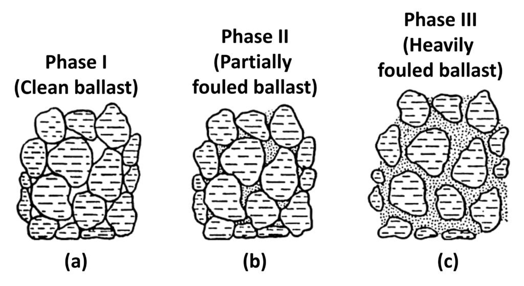
According to Huang et al. (2009), fouling of rail track ballast progresses in three phases, as illustrated in Figure 1. Phase I pertains to a clean or very slightly fouled ballast sample with almost all aggregates establishing contact with each other at the aggregate surface to sufficiently carry the load. In turn, Phase II will have the voids in between aggregates filled with enough fine particles to significantly reduce the strength of the material; however, aggregate-to-aggregate contact is maintained. Lastly, in a Phase III fouled ballast condition, because of the excessive amount of fine particles, aggregate-to-aggregate contacts are mostly eliminated, and the aggregate particle movements are then constrained only by the fine particles filling the matrix or voids between the particles.
Figure 1. Three phases of ballast fouling.
The decay of mechanical performance of ballast in response to fouling is well-documented. Indraratna et al. (2011) tested fouled ballast and argued that fouling reduces interparticle friction, which then reduces shear strength, and once fouling reaches a significant level, ballast exhibits an increasingly ductile behavior. Using direct shear tests, Danesh et al. (2017) found that by increasing ballast breakage ratio (a measure of ballast degradation) by 21% at a fixed normal stress, peak shear strength and peak friction angle were found to decrease by nearly 50% and 30%, respectively.
Huang et al. (2009) conducted a comprehensive laboratory testing program to assess the effects of three different fouling agents – coal dust, plastic clayey soil, and mineral filler – on railroad ballast strength. Using direct shear tests, Huang’s group investigated the strength and deformation characteristics of granite-type ballast at various degrees of fouling under both wet and dry conditions. Those workers found that, among the specimens studied, the clean ballast samples had the highest shear strengths at all studied normal stress levels, and increased fouling invariably led to reduction in shear strength. Coal dust was by far the worst fouling agent tested by Huang’s group, as it led to the most drastic decreases in shear strength, especially at high fouling levels.
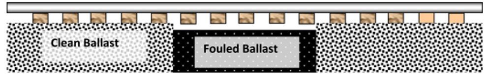
The deleterious effect of coal dust had already been documented by Budiono et al. (2004), who found that coal-fouled ballast may exhibit greater plastic settlement in response to cyclic loading than fresh ballast under similar conditions. Huang and Tutumluer (2011) conducted Discrete Element Modelling simulations to further assess this phenomenon and went on to report that, in response to successive cyclic loading, coal-fouled ballast accumulated settlement much more rapidly than clean ballast. The differential settlement behavior in clean and fouled railway segments may lead to the development of so-called ‘hanging tie’ (Figure 2), which makes the track susceptible to mechanical buckling. Recently, Ngamkhanong et al. (2021) used 3D Finite Element Modelling to demonstrate that even mild ballast fouling can increase the likelihood of track buckling and reduce the maximum allowable temperature for track stability.
Figure 2. ‘Hanging tie’ in response to uneven ballast fouling.
Predictably, the drainage capabilities of ballast are also hindered by fouling. Tennakoon et al. (2012) noted that even a modest increase in Void Contamination Index (VCI) may lead to a significant decrease in the hydraulic conductivity of ballast; Indraratna and Ngo (2018) performed constant-head permeability tests with a large-scale permeameter and found that a 5% increase in VCI caused the hydraulic conductivity of ballast to decrease by factors of 200 and 1500 for ballast contaminated by coal and fine clayey sand, respectively. Beyond a certain VCI limit, the hydraulic conductivity of fouled ballast may converge to the hydraulic conductivity of the fouling materials themselves.
2. Indices of ballast fouling
Four particularly important indicators of fouling are used by the railway community: the percent passing, the Fouling Index (FI), the Percentage Void Contamination (PVC), and the Void Contaminant Index (VCI).
Percent passing. This is the simplest index of ballast fouling. As the name implies, it measures the degree of fouling by the percentage of material passing a certain sieve size, usually the No. 4 sieve (opening size of 4.76 mm or smaller). Typical ballast gradation specifications limit the amount of material smaller than this size as delivered; therefore, the amount of material passing the No. 4 sieve is often related to the degree of fouling (Li et al., 2015).
Fouling Index. Selig and Waters (1994) defined the Fouling Index (FI) as a summation of the percentage (by weight) of ballast particles passing through the 4.75 mm and 0.075 mm sieves. Accordingly, the FI is stated as

where P4 is the percentage by weight of particles passing the No. 4 sieve (4.75 mm) and P200 is the percentage by weight of particles passing the No. 200 sieve (0.075 mm). As the keen reader will notice, FI reflects the importance of fines content by accounting for them twice, a first time through P4 and again through P200. Selig and Waters (1994) deliberately conceived the FI in this manner to reflect the greater role of fine materials in the fouling process. Experimental work by Qian et al. (2014) indicated that the FI is a good metric of ballast fouling conditions, in that, as FI approaches 40, nearly all voids in large-particle ballast are filled with finer materials stemming from ballast degradation.
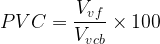
Percentage Void Contamination. One important shortcoming of the Fouling Index has been identified by stakeholders in Australia, a country where coal is a common payload and hence coal fines are prominent fouling agents. The specific gravity of coal ash is only about half of the SG of aggregate rock particles, so the volume of coal ash in the fouled ballast will be twice that of rock particles for the same value of ‘percent passing’ because this latter parameter is based on weight instead of volume. In view of this limitation, Feldman and Niessen (2002) defined the Percentage Void Contamination as the ratio of bulk volume of fouling material (Vvf) to the initial voids volume of clean ballast (Vvcb),
As noted by Stark et al. (2017), the primary benefit of PVC over FI is its better ability to predict fouled ballast behavior when coal ash is the fouling material. This becomes clear when comparing cyclic triaxial tests of ballast fouled with coal ash and ballast fouled with crushed ballast particles. Identical fouling volumes of coal ash and crushed ballast are added to identical ballast material. This results in equal values of PVC, which is based upon volume measurements, but the FI values are markedly different, namely 10 for the ballast contaminated with coal ash and 20 for the ballast contaminated with crushed ballast. This is problematic because both ballast samples exhibit similarly unacceptably large permanent strains during cyclical triaxial loading even though the coal ash sample would be expected to exhibit better performance because its FI is one-half of the FI of the crushed ballast sample. This suggests that parameters based on volume, such as the PVC, are better indicators of fouled ballast performance than weight-based metrics such as the percent passing, especially when coal ash is involved.
Void Contaminant Index. A final noteworthy parameter is the so-called Void Contaminant Index (VCI), which is a modification of the PVC that uses void ratio, specific gravity, and dry mass of the fouling agent and clean ballast material to better account for the nature of the fouling material. The VCI is defined as

where eb is the void ratio of the clean ballast, ef is the void ratio of the fouling material, Gcb is the specific gravity of the clean ballast, Gf is the specific gravity of the fouling material, Mb is the mass of the ballast material, and Mf is the mass of the fouling material. Of the indices discussed in this post, VCI is the only one that accounts for the specific gravity of the fouling material. While the VCI may require more detailed laboratory work for determination of specific gravity and other relevant properties, Tennakoon et al. (2012) argue that the extra effort is offset by the savings in track maintenance that would’ve been needed as a result of inaccurate assessment of fouling derived from mass-based indices only.
3. Ballast fouling and Discrete Element Modelling
Continuum-based models such as the Finite Element Method (FEM) or the Finite Difference Method (FDM) are the mainstays of numerical modelling in civil infrastructure. These models can be easily implemented with the plethora of commercial codes currently available and often require only moderate computational power. However, continuum techniques are unwieldy for analysis of railway ballast because this is a granular material, constituted of an assemblage of large solids (typical size 40 mm) interspersed with a substantial volume of voids. As such, ballast can be more reliably analyzed with Discrete Element Modelling (DEM), which provides a better understanding of particle shape or angularity, interparticle movements, breakage, contact force distributions, and other aspects of granular material behavior that cannot be easily investigated with continuum-based solutions. DEM has been shown to reasonably reproduce experimental ballast behavior, be it under static or cyclic loading (Lu and McDowell, 2010).
Wang et al. (2021) used a DEM code to investigate the mechanical behavior of fresh and fouled ballast subjected to direct shear loading. Wang’s group found that reducing the effective modulus (a micromechanical surrogate of Young’s modulus) and the interparticle friction coefficient can be used as means to represent, in a DEM numerical framework, the intrusion of fine material in ballast. Their simulations corroborated the now well-established notion that infiltration of fines can reduce the shear strength of ballast.
Similar findings were reported by Indraratna et al. (2014), who used a DEM code to simulate the stress-strain behavior of clean and fouled ballast in direct shear tests. Coal fines were represented by the inclusion of fine spherical particles into the ballast voids; the degree of fouling was defined by the Void Contaminant Index (VCI), which varied from 20 to 70%. Figure 3 shows the initial DEM representation of the direct shear apparatus used by Indraratna’s group. Those workers found that not only do coal fines reduce the shear strength of ballast as a result of reduced interparticle friction, they can also increase the dilation of the fouled ballast, especially at low normal stresses. Of note, one the DEM simulations conducted by Indraratna et al. (2014) to reproduce experimental results of a direct shear test required nearly 500 hours in a high-performance workstation, offering evidence that discrete element modelling can be much more computationally expensive than continuum-based models in similar settings.
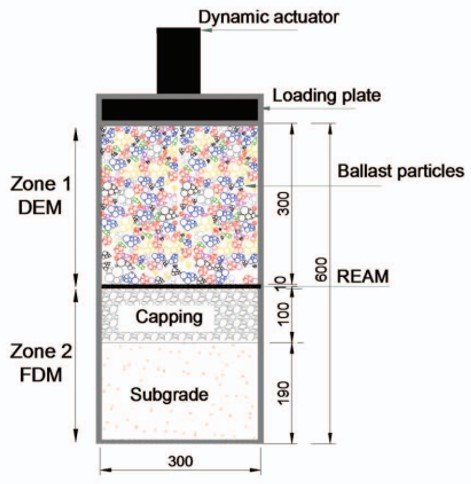
DEM can be coupled with other numerical techniques to extend the discrete-element framework to other components of the rail track. Indraratna et al. (2020) used a coupled discrete element method-finite difference method (DEM-FDM) to investigate the interaction of discrete ballast grains and adjacent continuum media, namely recycled rubber energy-absorbing mats (REAMs), capping (subballast), and subgrade. Figure 4 shows a schematic diagram of the coupled discrete-continuum system adopted by Indraratna’s group. As shown, the ballast layer was represented by a two-dimensional assortment of cylindrical particles. Ballast grains were simulated by bonding of these elements, and the breaking of these bonds was considered to represent particle breakage. Cyclic loading of the discrete-continuum system at various frequencies was simulated and compared with newly obtained data from cyclic triaxial tests. Those workers found good agreement between experimental and numerical results. Ballast breakage was observed to increase with loading frequency, and most bond breakage was concentrated in the first few thousand loading cycles. The inclusion of recycled REAMs was found to result in decreased deformation and degradation of ballast, as they effectively reduced the energy transferred to ballast grains.
Figure 3. Initial assembly of large-scale direct shear test with irregular-shaped particles as developed by Indraratna et al. (2014). (a) Fresh ballast; (b) 40% VCI fouled ballast.
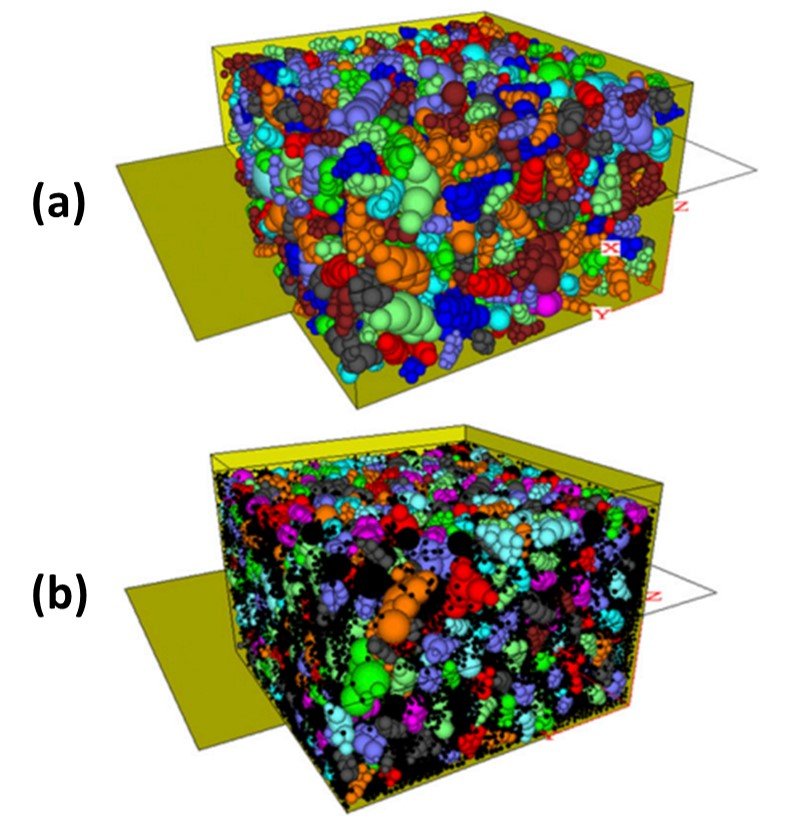
Figure 4. Discrete-continuum 2D model developed by Indraratna et al. (2020). Zone 1 is the DEM region used to represent the ballast layer. Zone 2 is the continuum region constituted of REAM, capping (sub-ballast), and subgrade.
References
The references list will be posted on May 26, 2023.

