
In this article, we briefly introduce two of the most common erodible open channel design methods: the maximum permissible velocity method and the tractive force method.
1. The maximum permissible velocity method
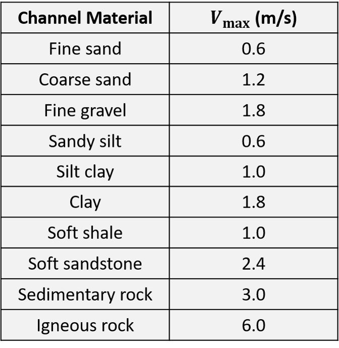
This method is based on the assumption that a channel will not be eroded if the average cross-sectional velocity in the channel does not exceed a maximum permissible value. The permissible velocity is defined as the mean velocity at or below which the channel bottom and sides are not eroded. Typical values, as prescribed by the US Army Corps of Engineers, are listed below.
Table 1. Suggested maximum permissible channel velocities
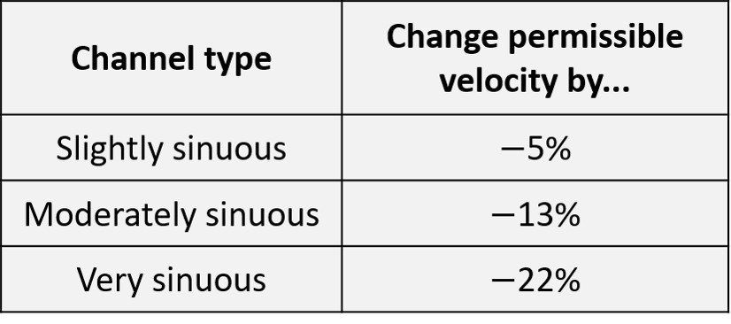
In principle, the values above apply to straight channels. For curved channels, the value of 
Table 2. Modification of permissible velocity for curved channels
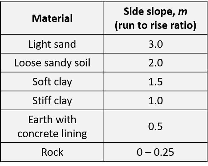
A channel design procedure would be incomplete without the prescription of a side slope. Some reference values, compiled from Chaudhry (2008) and Akan (2006), are listed below.
Table 3. Recommended side slopes
To allow for waves and water surface disturbances, a suitable amount of freeboard should be provided. A rough estimate for freeboard, as recommended by the US Bureau of Reclamation, is to use the formula

where 

In a typical channel section sizing problem based on the permissible velocity method, we proceed as follows.
Step 1. For the specified channel material, determine the Manning’s n, the side slope m, and the maximum permissible velocity
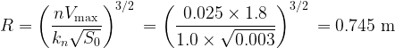
Step 2. Compute the hydraulic radius using the Manning formula,

where n is Manning’s roughness factor, 

Step 3. Compute the required flow area as 

Step 4. Compute the wetted perimeter as 

Step 5. The cross-sectional area for a trapezoidal cross-section is given by
while the wetted perimeter is
In view of these two expressions, substitute the known variables and solve simultaneously for the bottom width B and the flow depth y.
Step 6. Check the Froude number. Results may be questionable if flow is supercritical, i.e., if 
Step 7. Add a freeboard and modify the section as needed.
Example 1
An unlined, straight channel to be excavated in fine gravel will convey a discharge of 8 m³/s over a longitudinal slope of 0.003. Manning’s n for the soil is 0.025. Proportion the section dimensions using the maximum permissible velocity method. Use a slope of 1 H : 1 V.
The maximum permissible velocity for a fine gravel is
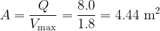
The required cross-sectional area is
and the wetted perimeter follows as
Since, for a trapezoidal channel,
and
we have, for the present case,

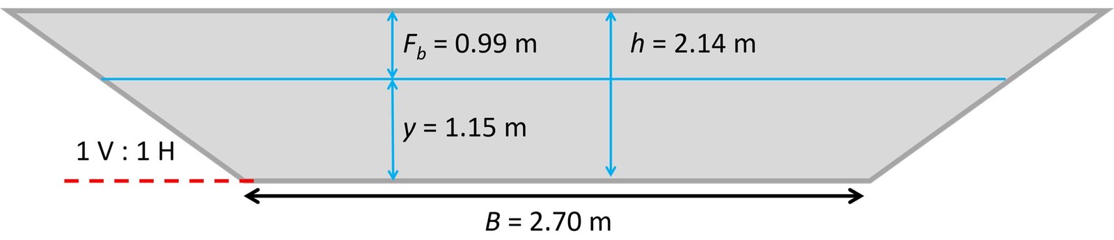
These equations can be solved simultaneously to yield B = -0.000324 m, y = 2.11 m, which is preposterous, and B = 2.70 m, y = 1.15 m, which is a viable solution pair. The bottom width and flow depth of the channel have been established. To prescribe a freeboard for the channel, we obtain k = 0.853 by interpolation, with the result that

Accordingly, the channel has a total depth h = 0.99 + 1.15 = 2.14 m. The channel cross-section is illustrated below.
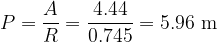
It remains to compute the Froude number. We first require the top width of the channel section, which is given by

The hydraulic depth is then D = A/T = 4.44/5 = 0.888 m, and the Froude number follows as
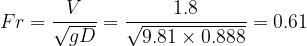
Since
2. The tractive force method
As compared to the permissible velocity approach, the scour and erosion process may be viewed in a more rational fashion by considering the forces acting on a particle lying on the channel bottom or the channel sides. The channel is eroded if the resultant of forces tending to move the particle is greater than the resultant of forces resisting the motion; otherwise, it is stable. Such is the rationale that underpins the tractive force method.
The permissible unit tractive force, 

Let us consider a channel with bottom slope 


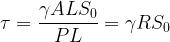
For very wide channels, we can conservatively estimate 

However, the tractive force distribution in the channel bed is not uniform. Although many estimates have been made to determine this distribution, results have not been conclusive. As an approximation, the shear on the sides of a trapezoidal channel can be estimated as 0.76
where 

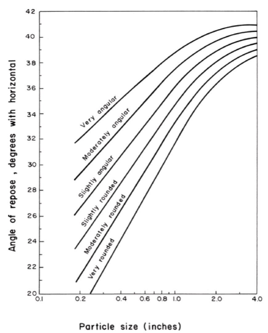
Figure 1. Angle of repose of noncohesive soil as a function of particle geometry.
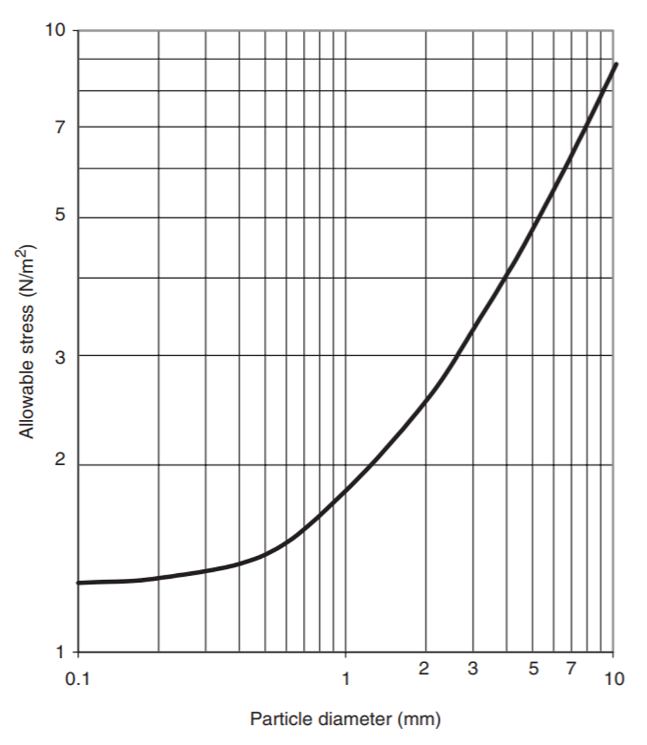
For noncohesive soils, the permissible tractive force is a function of the mean diameter of the channel material, as shown in Figure 2.
Figure 2. Permissible shear in noncohesive soil as a function of particle size.
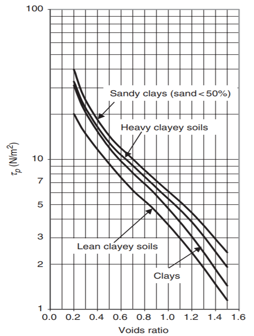
For cohesive soils, in turn, the permissible tractive force depends upon the voids ratio, as illustrated in Figure 3. A relation between
Figure 3: Permissible shear in cohesive soil as a function of voids ratio.
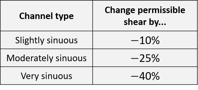
If the channel is not straight, the permissible shear must be reduced in accordance with the following table.
Table 4. Modification of permissible shear for curved channels
In a typical channel section sizing problem by the tractive force method, we proceed as follows.
Step 1. Select a side slope m. Then, for a channel in noncohesive material, read a permissible shear from Figure 2. For a channel in cohesive material, take
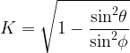
Step 2. For noncohesive material, compute the reduction factor K and determine the permissible stress on the sides by multiplying by K the permissible stress determined in step 1. The angle of repose may be read from Figure 1.
Step 3. Equate the permissible shear stress on the sides to 0.76
Step 4. Using the value of y obtained in step 3, along with the design discharge Q, Manning’s n and the side slope m, solve the Manning equation for the bottom width B.
Step 5. Check that the shear stress on the bottom,
Step 6. Check the Froude number. Results may be questionable if flow is supercritical, i.e., if
Step 7. Add a freeboard and modify the section as needed.
Example 2
As an example, suppose we wish to design a channel to carry a discharge of 75 m³/s. The bottom slope is 0.0002, and the channel is excavated through fine gravel having a particle size of 7.5 mm and Manning’s n of 0.023. Assume the particles are slightly rounded and the water carries fine sediment at low concentrations. The channel is slightly sinuous. Use a slope of 1 V : 3 H.
From Figure 2, the allowable stress for the particle diameter in question is 6.5 N/m². Since the channel is slightly sinuous, the permissible shear must be reduced by 10%, leading to a corrected allowable stress of 

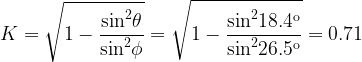
The permissible stress on the channel sides is then 
The unit tractive force on the side is 0.76

It remains to compute the bottom width B, which follows from the Manning equation,

![\displaystyle Q=\frac{1}{n}\times \left( {B+my} \right)y\times {{\left[ {\frac{{\left( {B+my} \right)y}}{{B+2\sqrt{{1+{{m}^{2}}}}y}}} \right]}^{{{2}/{3}\;}}}\times S_{o}^{{{1}/{2}\;}}](https://s0.wp.com/latex.php?latex=%5Cdisplaystyle+Q%3D%5Cfrac%7B1%7D%7Bn%7D%5Ctimes+%5Cleft%28+%7BB%2Bmy%7D+%5Cright%29y%5Ctimes+%7B%7B%5Cleft%5B+%7B%5Cfrac%7B%7B%5Cleft%28+%7BB%2Bmy%7D+%5Cright%29y%7D%7D%7B%7BB%2B2%5Csqrt%7B%7B1%2B%7B%7Bm%7D%5E%7B2%7D%7D%7D%7Dy%7D%7D%7D+%5Cright%5D%7D%5E%7B%7B%7B2%7D%2F%7B3%7D%5C%3B%7D%7D%7D%5Ctimes+S_%7Bo%7D%5E%7B%7B%7B1%7D%2F%7B2%7D%5C%3B%7D%7D&bg=ffffff&fg=000&s=0&c=20201002)
Substituting n = 0.023, m = 3, y = 2.79 m, S = 0.0002, and Q = 75 m³/s brings to
![\displaystyle \frac{1}{{0.023}}\times \left( {B+3\times 2.79} \right)\times 2.79\times {{\left[ {\frac{{\left( {B+3\times 2.79} \right)\times 2.79}}{{B+2\sqrt{{1+{{3}^{2}}}}\times 2.79}}} \right]}^{{{2}/{3}\;}}}\times {{0.0002}^{{{1}/{2}\;}}}=75](https://s0.wp.com/latex.php?latex=%5Cdisplaystyle+%5Cfrac%7B1%7D%7B%7B0.023%7D%7D%5Ctimes+%5Cleft%28+%7BB%2B3%5Ctimes+2.79%7D+%5Cright%29%5Ctimes+2.79%5Ctimes+%7B%7B%5Cleft%5B+%7B%5Cfrac%7B%7B%5Cleft%28+%7BB%2B3%5Ctimes+2.79%7D+%5Cright%29%5Ctimes+2.79%7D%7D%7B%7BB%2B2%5Csqrt%7B%7B1%2B%7B%7B3%7D%5E%7B2%7D%7D%7D%7D%5Ctimes+2.79%7D%7D%7D+%5Cright%5D%7D%5E%7B%7B%7B2%7D%2F%7B3%7D%5C%3B%7D%7D%7D%5Ctimes+%7B%7B0.0002%7D%5E%7B%7B%7B1%7D%2F%7B2%7D%5C%3B%7D%7D%7D%3D75&bg=ffffff&fg=000&s=0&c=20201002)
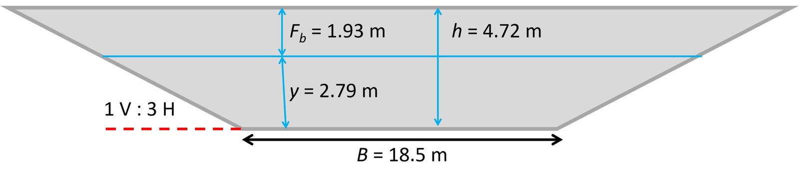
Solving the equation above yields B = 18.5 m.
We proceed to verify that the shear stress on the bottom does not exceed our permissible stress. The shear stress on the channel bottom is

This is less than

The total channel depth is then h = 1.93 + 2.79 = 4.72 m. The final channel is illustrated below.
Checking whether or not the Froude number exceeds unity is left as an exercise to the reader.
Go further
Montogue offers a free set of solved problems on hydraulic structures and design of open channels, which you can find here. Hydraulics students may also be interested in our quiz on specific energy and momentum. Check it out!
References
• AKAN, A. (2006). Open Channel Hydraulics. Oxford: Butterworth-Heinemann.
• CHAUDHRY, M. (2008). Open-Channel Flow. 2nd edition. Heidelberg: Springer.