
1. HAWTs versus VAWTs
Wind turbines can be classified in several ways, but the most common classification scheme is based on the turbine’s axis of rotation: if the rotor axis is parallel to the direction of the prevailing wind, the turbine is a horizontal-axis wind turbine or HAWT; if, in turn, the rotor axis is perpendicular to the prevailing wind, we have a vertical-axis wind turbine or VAWT.
A second approach to classification of wind turbines concerns the nature of the aerodynamic forces that drive the turbine blades. In drag-based turbines, the driving aerodynamic force is in the direction of airflow; Savonius-type VAWTs are drag-based devices. In lift-based turbines, the aerodynamic force is perpendicular to the direction of airflow; HAWTs and Darrieus-type VAWTs are lift-based in nature.
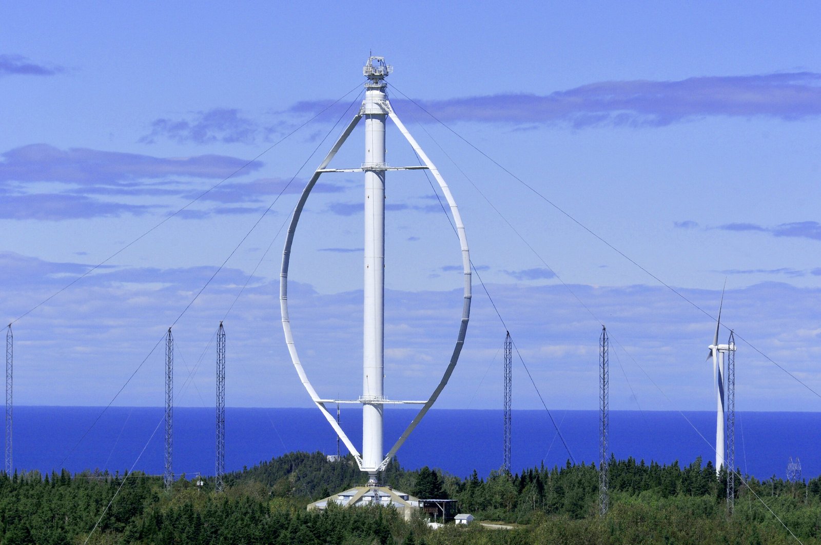
Figure 1 shows three common types of VAWT.
Figure 1. Vertical-axis turbine designs: (1) Savonius-type; (2) ‘egg-beater’ Darrieus-type; (3) ‘H-rotor’ Darrieus-type.
The main difference between VAWTs and HAWTs is that VAWTs are omnidirectional, i.e., they can accept wind from all directions. This enables engineers to do away with a yaw system, which is costly, requires its own power, and could fail during operation. Also, VAWTs are much more tolerant of the wind conditions in their operation site; turbulence and rapidly shifting winds may cause HAWT productivity to deteriorate, but are less of a hazard for VAWTs.
The vertical rotational axis of a VAWT allows the generator to be located at the bottom of the tower. This makes installation, operation, and maintenance much easier. The tower can be lighter for a VAWT because the nacelle is excluded, which reduces structural loads and problems with erecting the tower.
The machinery associated with a VAWT can be made simpler still by introduction of a direct drive, a system whereby the turbine is connected, by dint of a shaft, to the rotor of the generator, with no need for a gearbox. Gearboxes are associated with breakdown and constitute a source of losses comparable to those of the generator. Direct drives also reduce the torsional constraints on the drive shaft imposed by eigenfrequency oscillations and thereby enable the shaft to be slimmer than if a gearbox had been used.
The blades of a HAWT are subject to a gravity-induced reversing stress at the root of the blade, which is not the case for VAWT blades. This is believed to be the main limitation for increasing the size of HAWTs. The blades of a HAWT are also subject to periodical loads due to wind shear, which may cause fatigue of the blades.
There are two main sources for wind turbine noise: aerodynamic noise from the tips of the turbine blades and mechanical noise from the drive train components. In general, aerodynamic noise increases with increasing blade tip speed of a turbine and, since a VAWT usually has a tip speed which is approximately half the tip speed of a HAWT of the same size, they are expected to generate less aerodynamic noise. Moreover, since a VAWT has the drive train components at ground level, the possible noise from these parts will not propagate as easily as when the drivetrain components are situated on the top of the tower.
In view of the many advantages of VAWTs over HAWTs, one is compelled to ask why the overwhelming majority of modern wind farms are constituted of horizontal turbines. The main reason, arguably, is that our understanding of HAWTs is much more complete. It borrows from windmill technology, which has been available for over a thousand years. Its theoretical underpinnings, such as Froude-Rankine momentum theory, have been inherited from well-established principles of ocean engineering and early aerodynamics.
Vertical turbines, in turn, have not drawn nearly as much interest until very recently. Some large prototypes were introduced in the 1970s and 1980s, but and none made it to the broader energy industry. One reason has to do with materials: early VAWTs had blades made of aluminum, which has a mediocre fatigue resistance when compared to the glass- and carbon-fiber technologies used nowadays. But the main hurdle for the development of VAWTs is their inherently complex aerodynamics, which includes temporal/azimuthal variations of bound vorticity on the blades; blade-wake interactions and 3D wake characteristics; dynamic stall; and flow curvature. These phenomena call for sophisticated wind tunnel experiments and high-fidelity CFD modelling.
2. Savonius-type VAWTs
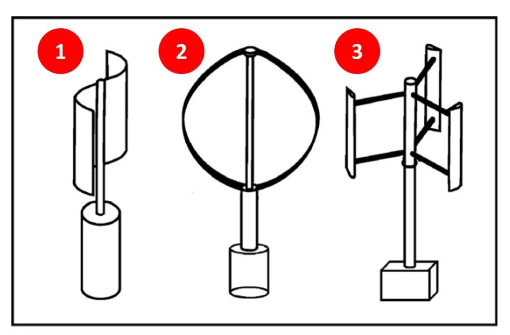
The Savonius VAWT was introduced by the Finnish engineer Sigurd J. Savonius in 1922. The Savonius rotor is arguably the simplest VAWT design; it consists of two half-cylinders facing opposite directions, as illustrated in Figure 2. In contrast to so many other VAWT designs, the Savonius is able to self-start. The main limitation is its low efficiency; one Savonius rotor patent filed in 1996 reported a power conversion efficiency of 24.4% (Benesh, 1996). More recently, Roy and Saha (2015) proposed a novel Savonius turbine design with maximum power coefficient equal to 0.31. (For comparison purposes, a modern HAWT has power coefficient ranging from 0.40 to 0.50.)
Some workers have attempted to improve efficiency of Savonius rotors by adopting helical or twisted blades, whereas others have added guiding plates or vanes in front of the turbine to improve flow conditions. Mohamed et al. (2011) combined some of these modifications in a novel Savonius design. An obstacle plate was introduced to partly shield the returning blade, and an optimization routine was carried out to find the position and size for the obstacle; a second optimization procedure was conducted to obtain the best blade shape, i.e., the one associated with the highest power coefficient. Mohamed’s optimal design was shown to have a power coefficient nearly 39% greater than a standard Savonius at the same tip speed ratio.
Wenehenubun et al. (2015) studied the effect of number of blades on Savonius turbine performance; rotors with two, three, and four blades were tested in a CFD scheme. Wenehenubun’s group reported that the three-bladed model exhibited the highest rotational speed and tip speed ratio, while the four-bladed model was associated with the greatest torque.
Figure 2. Savonius-type VAWT.
3. Darrieus-type VAWTs
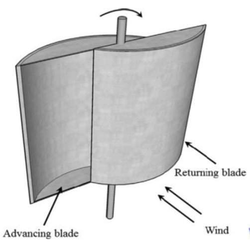
Georges J.M. Darrieus, a French engineer, patented the rotor design that now carries his name in 1931. Figure 2 shows two common variants of the Darrieus turbine: the ‘egg-beater’ and the H-rotor. In general, Darrieus turbines can extract more energy from the wind per unit area than Savonius turbines (Kumar et al., 2018; Gouriérès, 1982).
In the H-rotor, the blades can be simple in design, with a constant section along the span without twist or taper. This simple design is a boon for manufacturing and maintenance purposes, but comes at the cost of high bending moments. That said, the main limitation of the Darrieus is that many designs are unable to self-start, and thus require an initial power input before entering operation. Still, this is not necessarily true and hinges on the very definition of ‘self-starting’, as discussed in Du et al. (2019). Turbine starting behavior was investigated by Hill et al. (2008), who conducted wind tunnel experiments with a fixed-pitch H-rotor. In Hill’s experiments, the turbine rotor was held stationary until the wind tunnel’s speed had stabilized at its predetermined value. The release of the rotor triggered the start of the data capture process. Each trial began from a random starting position and it was found that the angular position had no appreciable effect on behavior. Most importantly, Hill’s experiments demonstrated the unaided start-up of a fixed-pitch H-rotor under steady atmospheric conditions. Similar findings were reported by Dominy et al. (2007), whose own experimental work with a three-bladed H-rotor demonstrated a lack of directionality and a capability for unaided self-starting in steady winds.
Solidity plays an important role in Darrieus-type VAWTs. The solidity of an H-rotor turbine is usually defined as the ratio of blade area to turbine swept area. Early research has shown that increases in solidity would result in greater blockage of the flow, causing a reduction of the incoming flow velocity and local changes in flow direction as more flow has to pass around the device. These blockage-induced direction changes result in lower angles of attack in the upstream half of the rotor, allowing the flow to remain unstalled at lower tip speed ratios (
Figure 3, Darrieus-type VAWTs.
4. VAWT arrays
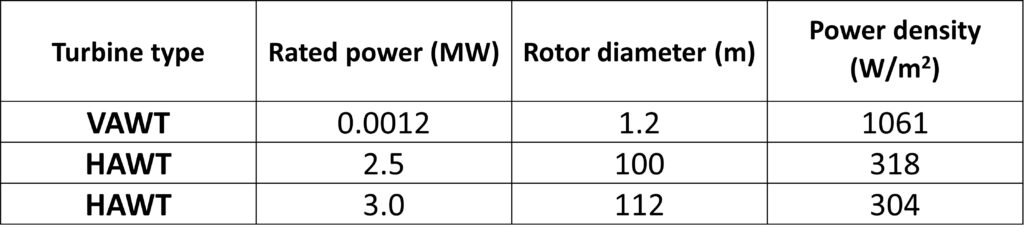
In HAWT wind farms, individual turbines must be placed at relatively large distances from one another so as to avoid undesirable interactions between incoming flow fields and wakes. To maintain 90% of the performance of isolated HAWTs, the turbines in a HAWT farm must be spaced 3 to 5 diameters apart in the cross-wind direction and 6 to 10 diameters apart in the downwind direction. The power density of these wind farms, defined as the power extracted per unit land area, is between 2 and 3 W m‒2, which compares poorly with solar power plants (
Table 1. Comparison of VAWT and HAWT power density. The power density is calculated as the turbine rated power divided by the area of the circular footprint swept by the turbine rotor blades when rotated in yaw by 360o. From Dabiri (2011).
.
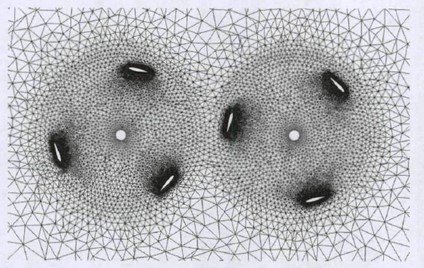
Research on aerodynamics of VAWT arrays is a recent topic. Of course, the simplest approach to the subject is to investigate the aerodynamics of two closely-spaced turbines. In a patent filing, Nason (2004) claimed that putting a pair of VAWTs in a counterrotating configuration can yield greater aerodynamic efficiency through vortex interaction between adjacent rotors. Korobenko et al. (2014) used the ALE-VMS finite element technique to simulate two adjacent counterrotating VAWTs, and found that combined operation led to a slight drop in the predicted aerodynamic torque; Figure 4 shows the mesh used by those workers. In contrast to Korobenko’s group, Ahmadi-Baloutaki et al. (2016) used wind tunnel experiments to show that installing two side-by-side turbines in a counterrotating configuration resulted in a slight increase in aerodynamic performance relatively to lone turbine operation.
Chen et al. (2017) conducted exhaustive numerical simulations of two adjacent straight-bladed VAWTs and used the Taguchi method to optimize their power output. Chen’s group found that, of the variables considered, power output was most affected by tip speed ratio and incoming flow angle. The dual turbine scheme, when operating under optimal conditions, achieved a power enhancement of nearly 10% relatively to lone turbine operation.
Recently, research groups have published models on operation of multiple-turbine columns and arrays. Duraisamy and Lakshminarayan (2014) used RANS simulations to show that, for VAWTs arranged in multiple columns, the downstream columns can be more efficient than the leading column. Bremseth and Duraisamy (2016) conducted comprehensive numerical simulations of isolated, pairs, columns, and arrays of VAWTs with an unsteady RANS solver. Each turbine in an infinite column of co-rotating VAWTs was shown to provide between 50 and 100% of power augmentation compared to an isolated VAWT. It was also shown that in an array of VAWTs, downstream turbines can be more efficient than upstream turbines.
In an interesting application of biomimetics to wind energy research, Whittlesey et al. (2010) proposed a VAWT array configuration based on the arrangement of shed vortices in the wake of schooling fish. They introduced a so-called array performance coefficient, CAP, to compare the average power output of an array configuration to that of a spatially isolated VAWT; values of CAP as large as 1.4 were reported for some array settings. Most substantial, however, was the close spacing between VAWTs afforded by the fish school-inspired model, which resulted in array power density increases of over one order of magnitude compared to equivalent HAWT wind farms.
Figure 4. Two-VAWT mesh used by Korobenko et al. (2014).
5. Urban VAWT farms
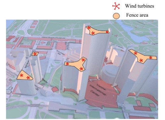
Recently, researchers have recommended the installation of small-scale wind turbines over and around high-rise buildings as a potential renewable power solution (Figure 5). Deployment of horizontal-axis turbines in urban environments is hindered by several factors, including low productivity in turbulent wind fields, high aeroacoustic noise, and aesthetic concerns. Also, when HAWTs are installed over tall buildings, mechanical loads and vibration imparted on the underlying structure are also of concern (Kooiman and Tullis, 2010). Most, if not all, of these issues can be overcome with VAWTs.
Li et al. (2021) evaluated the effect of rotor solidity and other characteristics on the power output of dual VAWTs with different rotor spacings in an urban environment. Predictably, a combination of dual VAWTs with high rotor solidity was shown to be more suitable for installation in areas with lower wind power density, and, conversely, a pair with lower rotor solidity was recommended for high-wind-power areas. The utilization of urban wind resources, Li’s group argued, could be optimized by synergistically combining building rooftop geometry to VAWT farm design variables such as rotor spacing and solidity. While Li’s research focused on two-turbine combinations, perhaps future research should focus on the integration of entire VAWT farms in the built environment.
Of course, implementation of urban VAWT projects cannot proceed without local stakeholders’ approval. Aiming to gauge public opinion on this matter, Khorsand et al. (2015) surveyed 350 people in OECD and non-OECD countries and found high levels of acceptance for urban wind energy projects. Interestingly, Khorsand’s group found that, in surveyed countries that had the greatest installed wind capacity, participants exhibited greater sensitivity towards the level of community involvement. That is, survey respondents in these countries reported higher levels of acceptance for wind energy projects under conditions when they were proposed to be built by the community rather than when they were proposed to be built by an energy company. More recently, Hui et al. (2018) conducted polls on the acceptance level of VAWTs in California and found that many respondents’ perception of VAWTs was closely associated with potential higher costs and potential harm to wildlife. Hui’s group therefore argued for a greater urgence in introducing new, more efficient VAWT designs in timely fashion, and also for further research on their ecological impact.
Figure 5. Deploying VAWTs on the rooftops of tall buildings. From Li et al. (2021).
References
Download references list here.